Liberating PC
0. Preparation and optional steps
Optional steps are marked as optional, all the other ones are mandatory. Also review Part I. of this series.
SSD (optional 69,99€) - you might want to keep the original disk, but SSD will speed it up significantly.
I've chosen Silicon Power SSD S55 240 GB, due to its price and performance. It's often performing in the same performance level as more expensive models. You can read the review for example here Silicon Power SSD review (czech language), or you can find the reviews in your language on the internet. One note: according to the reviews the 240GB version perfoms better than the 120GB one.
OS and installation media - I have created bootable live USB with Trisquel 7 on it. I'm not using CDs for installation due to the speed and also using the USB is more convenient in terms of experimenting with various OS installations. I've used tool called Unetbootin to create the live bootable USB, but there are many other ways on how to do it using plenty of different tools and using Windows/GNU+Linux or MacOS. The reason to choose Trisuqel was that it seems to be widely used in the community which (hopefully) means better support. You can also choose different OS which is fully free when you take a look on the list in the 1st part of this series.
Installation of Trisquel 7 - I have installed it on the SSD right after I replaced it. The replacement of HDDs itself takes few minutes. I want to have the Trisquel installed before I flash the Libreboot just to be sure, although nowadays it's possible to reinstall OS when using Libreboot without reflashing the ROM. Installation itself is pretty straightforward - you can find the guide here.
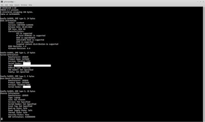
Determining the ROM size (optional) - This step is optional if you're going to follow my recommendations to buy both 8 and 16pin SOIC clips because there are 2 possible ROM sizes available on these laptops - 8Mb (16pin) and 4Mb (8 pin). You can get the size by booting any live linux distro and running: dmidecode | grep ROM\ Size . My is 8MB one so now I know which SOIC clip to use without disassembling the laptop.
SOIC clips
GIANT WARNING - if you don't have HUGE amount patience and don't want to loose many hours trying I suggest you tu buy POMONA clips instead of the clips I've bought - Pomonca 5250 (8pin) and Pomona 5252(16pin). The reason I've bought SOIC clips from China was the price (cca 4x cheaper than Pomona). I did one mistake at the time of ordering as I didn't notice that the pins on chinese clips are way too close to each other to use them with the jumper cables without modification.
Comparation of Chinese and Pomona(blue) clips:
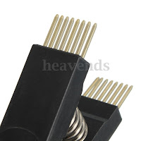

If you have already ordered the same clips as I did, or you just think that 20$ is way too much for 1 piece of little plastic thing, you will need to modify those clipsand wires as I did. The basic concept is to connect the jumper wires in the way that they they are isolated from each other so there is no short circuit at the end.
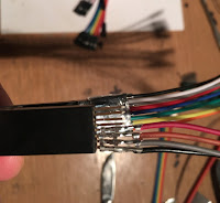
How I did it:
The first thing to do is to remove black plastic cover at one end from the jumper wires. After that you will need to use pliers to push the naked connector to make it thinner a little bit more to have enough space for all the jumper wires. If you push it too much you will not be able to conenct it to the clip pins. It takes some practice and few damaged/unusable wires to get used to it. Next step is to use heat shrinkable tube for every 2nd wire to insulate it. The reason to use it on every 2nd only is again to have as much free space between the pins as possible. I've bought the thinnest shrinkable tubes available in my city. Final step is to fix all the connected jumper wires altogether - I've used bigger heat shrinkable tube to fix them with the clip. The reason for this is simple - you don't want to touch exposed wires when flashing and you don't want the wires to be moving and potentially disconnecting from the clip during the manipulation.
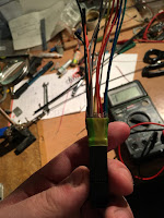
Of course you need to use multimeter to ensure that there's no short circuit at the end between any of the pins and to ensure that you have connectivity from the end of connected jumper wire and the corresponding connector on the clip. DO NOT try to flash the chip without verifying these with multimeter.

EC update - It is recommended that you update to the latest EC firmware version as per
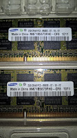
RAM (optional) - according to the specs and rules mentioned in Part I. I was able to buy 2x2GB for 20€ which are compatible with Libreboot.
Checking Odroid C1 GPIO compatibility with the Raspberry Pi - Odroid C1 specs . Since all of the tutorials on the internet are written for Raspberry Pi, I've decided to use my Odroid C1 to demonstrate it can be done with it as well. This is mandatory in order to know what to connect and where even though the GPIO on C1 is compatible with Raspbbery PI. I've put together excel table with pin layout and cable colors based on my setup on SOIC clip which is shown below.
SOIC clips
GIANT WARNING - if you don't have HUGE amount patience and don't want to loose many hours trying I suggest you tu buy POMONA clips instead of the clips I've bought - Pomonca 5250 (8pin) and Pomona 5252(16pin). The reason I've bought SOIC clips from China was the price (cca 4x cheaper than Pomona). I did one mistake at the time of ordering as I didn't notice that the pins on chinese clips are way too close to each other to use them with the jumper cables without modification.
Comparation of Chinese and Pomona(blue) clips:


If you have already ordered the same clips as I did, or you just think that 20$ is way too much for 1 piece of little plastic thing, you will need to modify those clipsand wires as I did. The basic concept is to connect the jumper wires in the way that they they are isolated from each other so there is no short circuit at the end.
How I did it:
The first thing to do is to remove black plastic cover at one end from the jumper wires. After that you will need to use pliers to push the naked connector to make it thinner a little bit more to have enough space for all the jumper wires. If you push it too much you will not be able to conenct it to the clip pins. It takes some practice and few damaged/unusable wires to get used to it. Next step is to use heat shrinkable tube for every 2nd wire to insulate it. The reason to use it on every 2nd only is again to have as much free space between the pins as possible. I've bought the thinnest shrinkable tubes available in my city. Final step is to fix all the connected jumper wires altogether - I've used bigger heat shrinkable tube to fix them with the clip. The reason for this is simple - you don't want to touch exposed wires when flashing and you don't want the wires to be moving and potentially disconnecting from the clip during the manipulation.
Of course you need to use multimeter to ensure that there's no short circuit at the end between any of the pins and to ensure that you have connectivity from the end of connected jumper wire and the corresponding connector on the clip. DO NOT try to flash the chip without verifying these with multimeter.


I. Laptop disassembling
I've used following video to disassembly the laptop fully. As mentioned in the Part I, the T400 model requires complete disassembly to expose the chip. Experienced user can do it in ~ 1 hour, so it may take few hours to disassembly it completely for non-experienced users. You can use following link to see step-by-step disassembly with photos as well. I have also taken some photos during the process with my smartphone as this model contains many small parts / cabling so I can use it later on when building it back .II. Locating the SOIC chip and connecting the SOIC clip
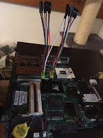
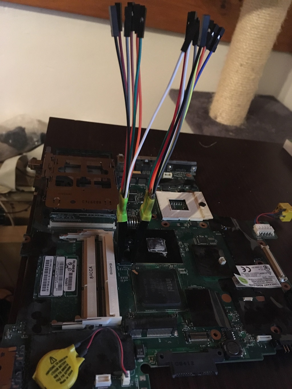
The chip itself is located between the chipset chip and ram slots as shown here (photos taken from here:


Second picure also shows the pin numbering and orientation on this 16pin chip. I have downloaded Odroic C1 GPIO specs and also the Macronix chip diagram:


Be sure to have your Odroid/Raspberry/any flashing device powered off before connecting the SOIC clip to the BIOS chip.
Odroid C1 GPIO numbering is printed on the board so it can be easily determined how to connect to the correct pins when using the previous tables:


After I have connected everything and checked 2-3 times if the order is correct I have turned on my Odroid C1. Btw I have Ubuntu 16.04 running on my Odroid, Also I have connected it to my LAN via ethernet cable so I can do the flashing remotely via SSH so I don"t have to attach any display to the Odroid.

So now when I have the modules loaded, I've tested to read the ROM chip afterwards which was not successful at a first time, so I had to power off Odroid, check if the clip is connected correctly and repeat the check again. Luckily it was successful for the 2nd time :) and I saw following:
"You might see errors, but if it says Verifying flash... VERIFIED at the end, then it's flashed and should boot. If you see errors, try again (and again, and again); the message Chip content is identical to the requested image is also an indication of a successful installation. "
Also it's recommended to use short jumper wires for better signal, in my case I've used 10cm ones, This makes the manipulation complicated though. But that's maybe why I've done it on the 1st attempt:
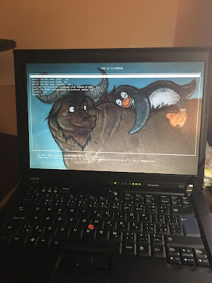
And a screenshot from Trisuqel 7 booted via Libreboot:

https://github.com/bibanon/Coreboot-ThinkPads/wiki/X200-X201-Hardware-Flashing
https://github.com/bibanon/Coreboot-ThinkPads/wiki/Hardware-Flashing-with-Raspberry-Pi
http://pi4j.com/pins/odroid-c1.html
III. Flashing
I suggest you to do everything as a root to have full permissions.
First thing to do was to download flashrom/other utilities needed and extract them:


I had to download libreboot ROM which had to match my bios chip size as well:

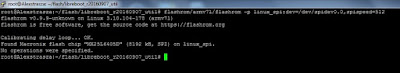
Then I needed to load SPI modules in order to be able to read/modify the ROM as I didn't see any spi device under /dev. After little bit of digging I've found following on Odroid forum, so I just had to execute following:
root@odroid:~# modprobe spicc
root@odroid:~# modprobe spidev
root@odroid:~# ls /dev/spidev0.0
/dev/spidev0.0
root@odroid:~#
root@odroid:~# modprobe spidev
root@odroid:~# ls /dev/spidev0.0
/dev/spidev0.0
root@odroid:~#

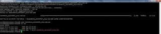
Next step was to change the MAC address inside the libreboot image to match the MAC of the integrated gigabit LAN I have on the T400. This MAC can be found either on the sticker located on the motherboard and/or sticker on the back of laptop. You can see couple of my typos :).

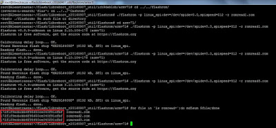
Of course, in case of any problems I had to do the backup of the original Lenovo ROM. This procedure also involves rom read check - saving at least 3 attempts to read the original ROM and comparing their md5sums. All the sums must mach and you must not continue without md5sums being the same for all the attempts. As you can see I had luck and all the attempts to read the ROM yielded into the same result and all the md5sums matched. So I was confident that the setup is 100% correct:

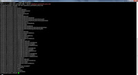
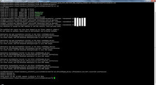
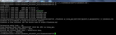
Now let's proceed to the flashing itself. I was lucky enough to get it flashed on the 1st attempt, but that's not always like that as per Libreboot documentation:
"You might see errors, but if it says Verifying flash... VERIFIED at the end, then it's flashed and should boot. If you see errors, try again (and again, and again); the message Chip content is identical to the requested image is also an indication of a successful installation. "
Also it's recommended to use short jumper wires for better signal, in my case I've used 10cm ones, This makes the manipulation complicated though. But that's maybe why I've done it on the 1st attempt:

IV. Assembling the laptop back.
Nothing special here, I just had to be careful as there are few tiny parts. Also I have changed the thermal grease for CPU and northbridge on the motherboard during the process.
As I was not sure whether the whole process was really successful I did try to boot it without palmrest and keyboard fully assembled back, I just connected the wires. Btw I've used the same video to assemble it as to disassemble it among with photos taken during the disassembling. Also photos from Libreboot documentation are helpful as well.
V. Boot it!
So I held my breath and pushed the power button. Voila ! It booted successfully :
And a screenshot from Trisuqel 7 booted via Libreboot:

Conclusion
Now I have my hardware paired with pure free software, but journey to the freedom is only at the beginning. There are many other challenges awaiting to free myself from the proprietary world where possible. I will share my progress here, so you can expect bunch of other blogs related to this topic in the future. I'm going to flash the MB with 4mb chip (8pin) as well so I will put a brief update here.
Sources used:
https://libreboot.org/docs/install/t400_external.htmlhttps://github.com/bibanon/Coreboot-ThinkPads/wiki/X200-X201-Hardware-Flashing
https://github.com/bibanon/Coreboot-ThinkPads/wiki/Hardware-Flashing-with-Raspberry-Pi
http://pi4j.com/pins/odroid-c1.html
No comments:
Post a Comment